Submitted to HEJ
Manuscript no.: MET-990617-A |  

 |
|
The scheme of upsetting between parallel plates is shown in Fig. 1.
Figure 1:
Work piece before and after upsetting
|
|
The points of the deformity zone can be given in a cylindrical system of
coordinates by the points  , where , where  , ,
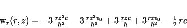
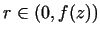 (see Fig. 1.).
We denote the velocity field by (see Fig. 1.).
We denote the velocity field by
![$w(r,z)=[w_r(r,z), w_z(z)]$](img34.gif) .
The components of .
The components of  can be determined by using the following model
assumptions: can be determined by using the following model
assumptions:
1. The material is incompressible.
2. The deformation is axisymmetric, that is
 |
(1) |
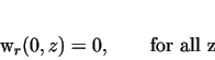
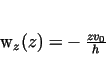
3.The  component of velocity at the contact of the piece and the plates is as follows: component of velocity at the contact of the piece and the plates is as follows:
 |
(2) |
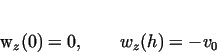
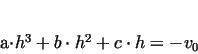
4. At  , ,  has a point of inflexion, that is, the deformation
velocity has a point of inflexion, that is, the deformation
velocity
 has an extremum at this point.
5. At has an extremum at this point.
5. At  the radial velocity component the radial velocity component  has a maximum when the work piece has a bilge form.
6. The upset material is homogenous and isotropic.
7. The has a maximum when the work piece has a bilge form.
6. The upset material is homogenous and isotropic.
7. The  -component of velocity can be written in the form of -component of velocity can be written in the form of
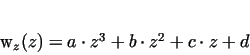 |
(3) |
because this function is the simplest assimetric one to describe the vwlocity field of the deformation
of the work piece.
Here  , ,  , ,  and and  are provisionally unknowns to
be determined.
From Assumption 3. we get that are provisionally unknowns to
be determined.
From Assumption 3. we get that
 |
(4) |
 |
(5) |
From Assumption 4.:
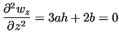 |
|
|
(6) |
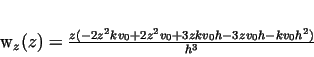
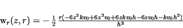
From equations (4, 5, 6), the values
of  and and  can be determined, whence: can be determined, whence:
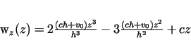 |
(7) |
Assumption 1. im;ies that the velocity field is divergence free:
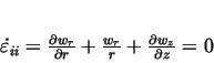 |
(8) |
By substituting the expression of  into his equation, for the
component of into his equation, for the
component of  we obtain first-order differential equation, that
contains we obtain first-order differential equation, that
contains  as a parameter. Condition 2. can be regarded as
an initial condition for this equation. So the problem given
by formulas (8) and (1) can be solved uniquely for every as a parameter. Condition 2. can be regarded as
an initial condition for this equation. So the problem given
by formulas (8) and (1) can be solved uniquely for every  . It is easy to see that
the solution is as follows: . It is easy to see that
the solution is as follows:
 |
(9) |
where  is a provisionally arbitrary constant to be determined.
Introducing the nondimensional parameter is a provisionally arbitrary constant to be determined.
Introducing the nondimensional parameter  by by
 |
|
|
(10) |
Equations (7,9) can be rewritten as:
 |
(11) |
 |
(12) |
Figure 2:
Radial component of the velocity at different values of  (
( , ,  , ,  ) )
|
|
In the above example, at  , the work piece remains cylindrical, while at , the work piece remains cylindrical, while at
 gets bilge and at gets bilge and at  the mantle surface of the piece
becomes concave. In case of convex shape, at the mantle surface of the piece
becomes concave. In case of convex shape, at  , the deformation velocity , the deformation velocity
 has a maximum, that is, has a maximum, that is,  is steepest in the
point of inflexion. (Fig.3). is steepest in the
point of inflexion. (Fig.3).
Figure 3:
Axial component of velocity at different values of  (
( , ,  , ,  ) )
|
|
In case  equations (11 and 12) gives the typical
forms of homogenous deformations, which is well-known, see e.g.
[2,3]: equations (11 and 12) gives the typical
forms of homogenous deformations, which is well-known, see e.g.
[2,3]:
 |
(13) |
 |
(14) |
The exact value of  can be determined by minimization the power
requirement of the forming. can be determined by minimization the power
requirement of the forming.
| Submitted to HEJ
Manuscript no.: MET-990617-A |
|
|
![\includegraphics[width=13cm]{Eps/Fig1.eps}](img30.gif)
![\includegraphics[width=9cm]{Eps/Fig2.eps}](img67.gif)
![\includegraphics[width=9cm]{Eps/Fig3.eps}](img82.gif)